Landyacht Performance Prediction

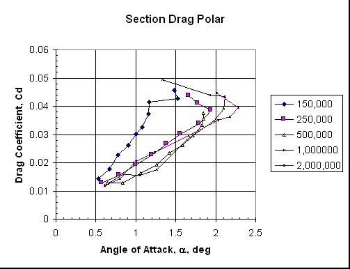
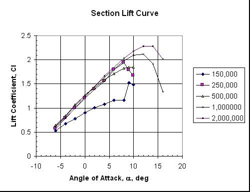
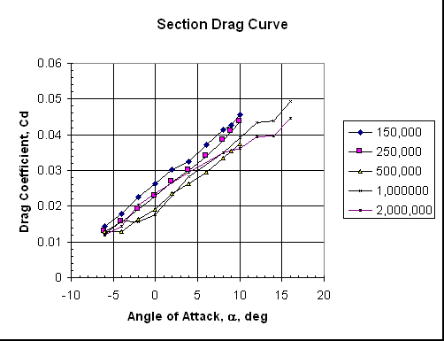
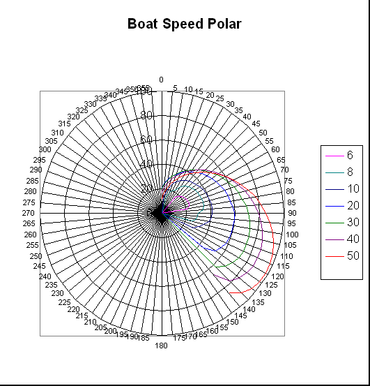
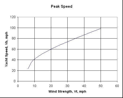
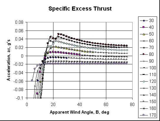
These charts show the predicted performance for a notional rigid winged landyacht. It conforms to the US Class IV open class rules. The wing section had a 30% chord slotted flap, and the main wing section was custom designed to provide high lift at low Reynolds numbers in conjunction with the flap.

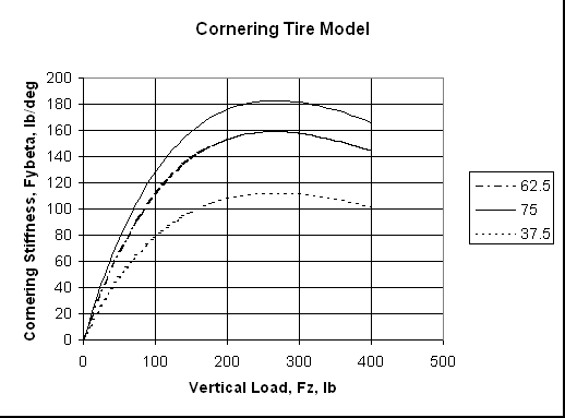
These results were calculated with a more sophisticated model than the simple MathCad model, but the basic relationships are the same. The principal difference was the use of tabular aerodynamic section data rather than the parabolic drag polar used in the MathCad model.
GW Gross Weight 400 lb
theta Angle Between Mast and Rear Wheel 15 deg
diam Wheel Diameter 3 ft
S Sail Area 59 ft^2
height Mast Height 25 ft
AR Aspect Ratio 10.59322
L 32.64775 ft
axle Width of Rear Axle 11.47103 ft
mu Tire Friction Coefficient 0.6
cbar Mean Wing Chord 0.903584 ft
e Oswald Efficiency Factor 0.9
CDbod Parasite Drag Coefficient for Chassis 0.15
Ki Induced Drag Factor 0.033387
epsilonw Angle Between Centerline, Front Wheel, and Rear Wheel 0.463648 rad
Hce Height of Center of Effort 14.25 ft
Ycg Lateral Location of Center of Gravity (to line between front and rear wheel) 8.55 ft
Xcg Longitudinal Location of Center of Gravity (from front wheel) 19.11838 ft
Xaxle Distance Between Front Wheel and Rear Axle 22.94206 ft
Dw0 Rolling Resistance Coefficient 0.02
Xce Longitudinal Location of Center of Effort 19.11838 ft
Dwv_125 Rolling Resistance Speed Factor 0

Boat Speed Polar

Peak Speed

Specific Excess Thrust

Section Drag Polar

Section Lift Curve

Section Drag Curve

Cornering Tire Model


Last Updated on 1/16/99
By Thomas E. Speer
Email: tspeer@gte.net

Home