![]()
Twin Wing Landyacht Concept
Goal - 100 kt/200 kph/120 mph with course racing landyacht
- Current World Record is 94 mph with one-way asymmetrical yacht
Problem - Landyacht speeds are limited by three factors:
- stability - rolling (heeling) moment limits available aerodynamic force
- skidding - tire traction limits available aerodynamic force
- efficiency - drag limits apparent wind angle (beta) which caps
Empirical Data -Limited
- Annual NALSA speed trials - historical yacht speeds & yacht speed/wind speed ratio
- SDSU wind tunnel test - rear wheels alone account for 30% to 40% of total aerodynamic drag
Design Approach - Twin Wing Concept
- Inclined wing, displaced from centerline, reduces effective moment arm
- Aerodynamic downforce adds to traction w/o adding inertia
- Structural load paths eliminate large bending moments in axle, body - lighter weight
- Delta wheel fairings
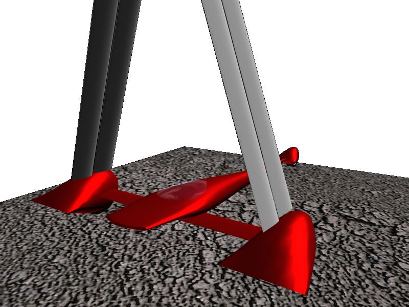
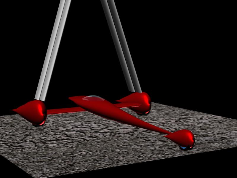
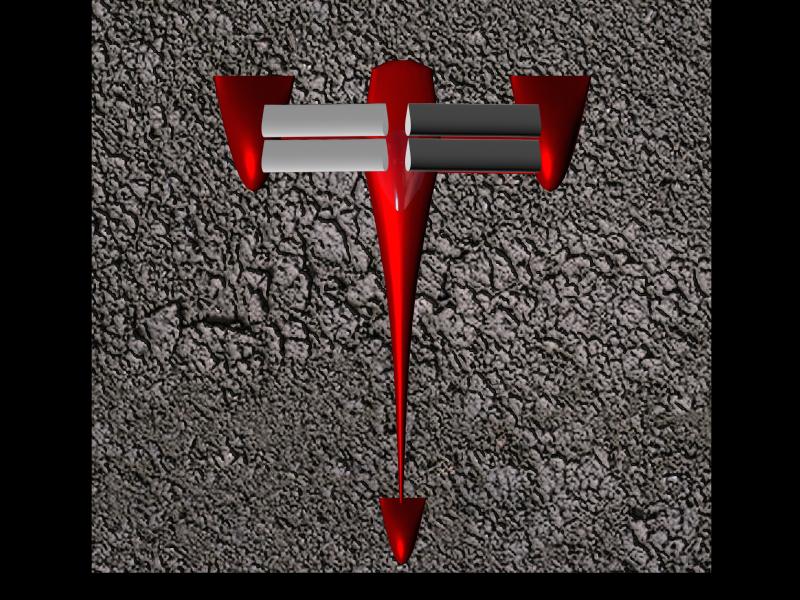
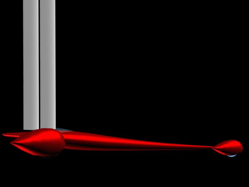
- Concept sketches:
rear quarter
front quarter
top
right side
front
rear
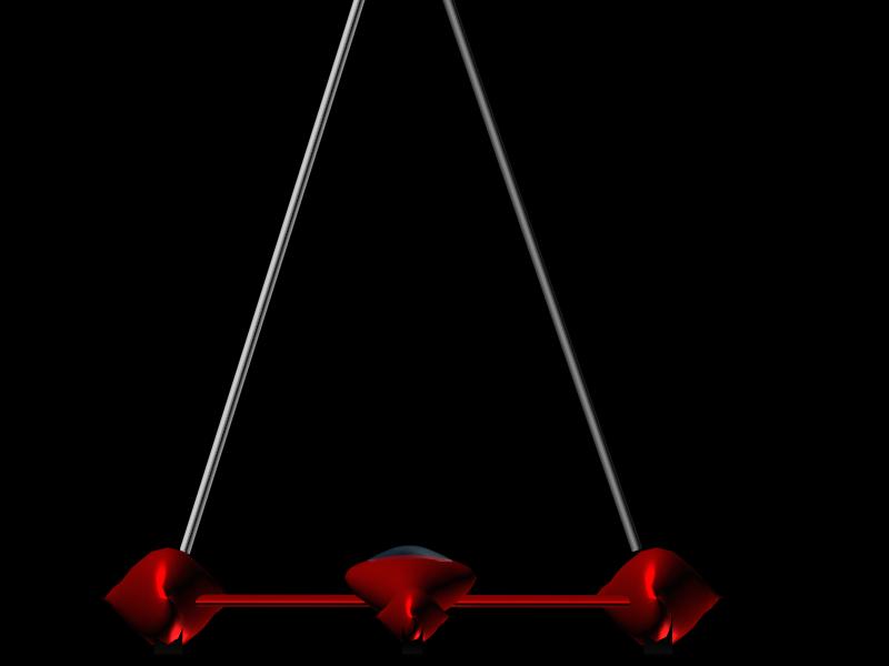
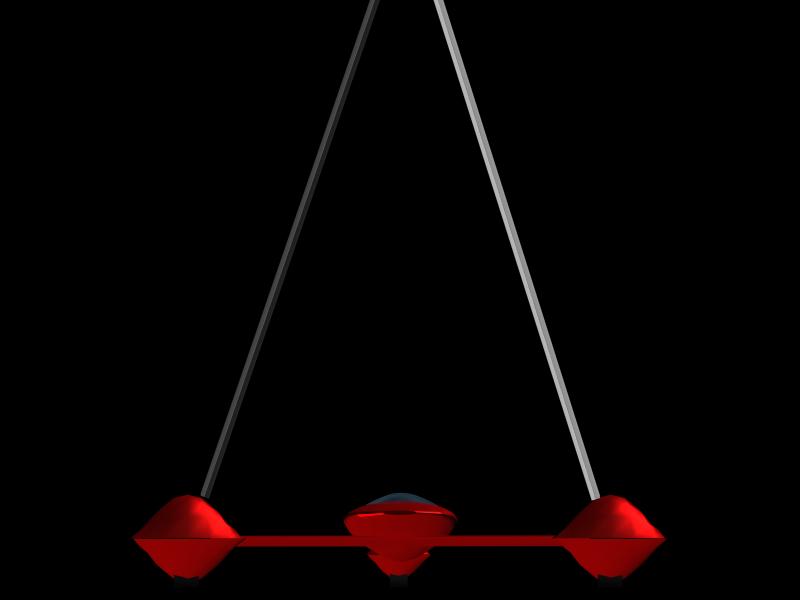
Twin Wing Rationale
- Consider a single wing, set to windward & inclined to leeward
- Projection of lift vector passes close to leeward wheel (Fig. 1)
- Force vector could pass through contact patch, producing zero moment
- Produces downward component
- Reflecting wing for other tack produces two, mutual supporting wings in an A-frame
- Pilot controls each wing separately to control rolling moments
- Initial feasibility looks promising, but light wind performance is a problem.
Delta Wheel Fairings
- Best landyachts today use simple flat plate over wheel hub - minimum "frontal" area
- Must work at + 15 - 30 degrees beta; zero beta drag is relatively unimportant
- Traditional fairings increase "frontal " area, do not consider separation due to beta
- Fat delta provides streamlined shapes in streamwise cutting planes
Aerodynamic Issues
- Fairing shaping for fully attached flow
- Wing/fairing & Wing/Wing interference
- Low Reynolds number performance
- Span/chord length tradeoffs (induced drag vs Reynolds number)
- Body shape
- Overall configuration sizing and optimization
Aerodynamic Tools:
- Eppler PROFIL: single element airfoil design
- MCARFA: multiple element airfoil analysis
- CMARC: 3D analysis
Tool Deficiencies:
- Mesh generation - difficult to handle wing/fairing geometry
- Multiple element airfoil design
- Inability to handle laminar separation bubbles or modest trailing edge separation
Progress to Date:
- 2D airfoil design
- Parametric study of 2 wings
- Representative fairings & wing intersections modeled